After a long wait, I just received from China the 4th axis for my router. Now it is time to install it.
Here I'm sharing my learnings, projects and experiences with CNC 3040 router/milling/cutting machine I have in my garage. Here I will include all the projects I will make with the Arduino processor and accessories. You are welcome to comment, and share.
Sunday, January 31, 2021
Fourth Axis
Friday, January 29, 2021
My version of the Hyperbola Clock
For this one, I used a standard high torque quartz mechanism.
The clock was fully modeled in Fusion 360. The base is oak and the disk and x-shape panel with birch 1/8" plywood. The moving bar is a brass 1/8" diameter rod.
All the wood parts were processed in my router and I used the wood lathe to finis the oak part.
For engraving the initials on the disk and the rod position reflection on the x-shape, I used a 5.5w led laser head attached to the spindle motor of my router.
The disc functions as the hour hand.
The minute's hand, the support for the brass rod, and the hour markers on the oak base are 3D printed using black PETG filament.
I love projects where I can use all my tech gadgets!
Wednesday, September 16, 2020
New conical Clock Model
Saturday, July 4, 2020
A plastic mold to make Arepas
Saturday, May 30, 2020
Fix it, Don't trash it!
Friday, May 15, 2020
The Suprematist Time Keeping Machine
![]() |
| The Suprematist Time Keeping Machine |
Many hours of work resulted in a model almost identical to the original. There is some small modification in the position of the hour's hand to avoid collision with the minute's hand and to reference a real-time relation between the hours, the minutes, and the seconds. The artist made the sculpture in a way that it almost shows a real hour!
Tuesday, May 12, 2020
Back to my garage (COVID-19) stay at home. New CNC controller for may 30/40 CNC router
During these difficult days, doe to my age and previous health conditions, I must stay at home.
My design workload that can be done from home is also low as my customers are also reducing their activities to the minimum necessary, so I am back to my garage.
After a few days of cleaning and reorganizing, I restarted a project that was on hold for a long time: Refurbish my CNC; I have been working on this project on and off for several months during my short home return from my frequent travel schedule.
The scope of the project is:
- New computer to control the machine
- Upgrade to MACH4 software
- New driver board compatible with MACH 4 and Ethernet connection
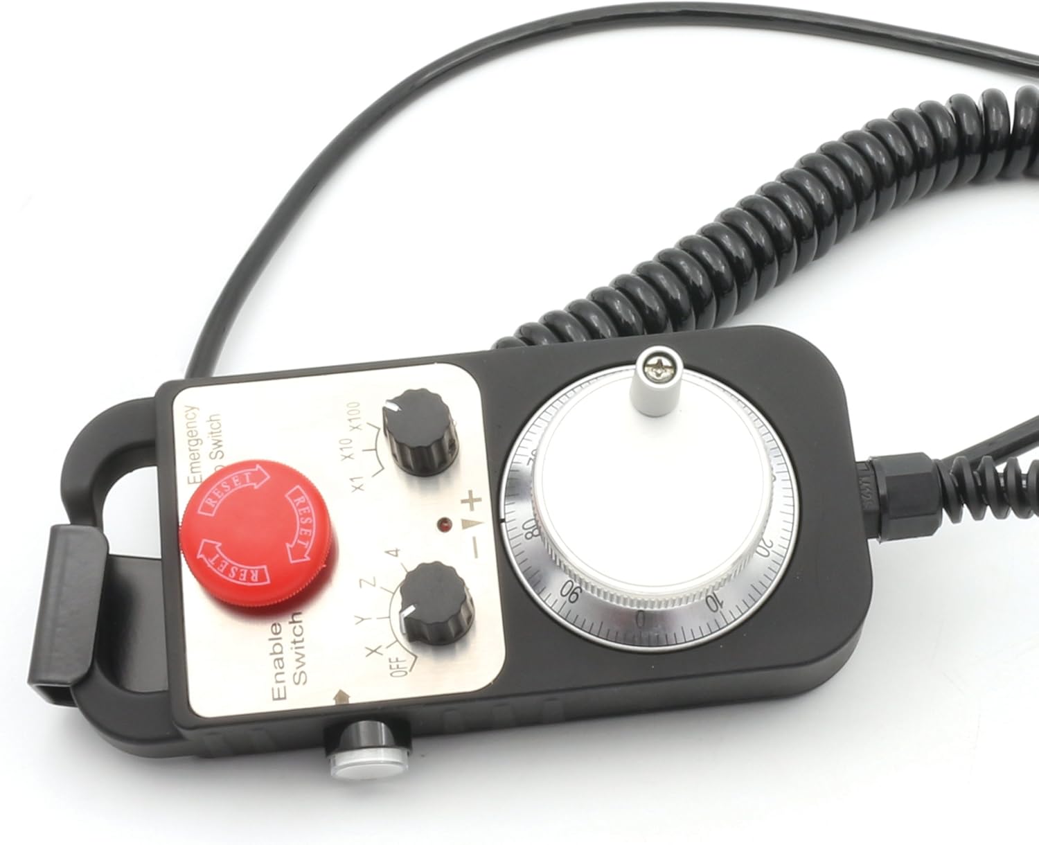
- Add a manual pendant.
- Mechanical maintenance of the router.
- Add limit/home switches.
- Add an Axis Z height probe.
- Add a rotary axis (B)
- Add a small laser head for engraving.
After in-depth investigation and some failed purchases of driver boards compatible with Mach4, I finally found a good one with a lot of documentation and support, the PoKeys57CNC Motion Controller for Mach4, and now, after using it for some time, I am sure I made the right decision.
The next step was to order all the components and design with Fusion 360 and fabricate the controller box.
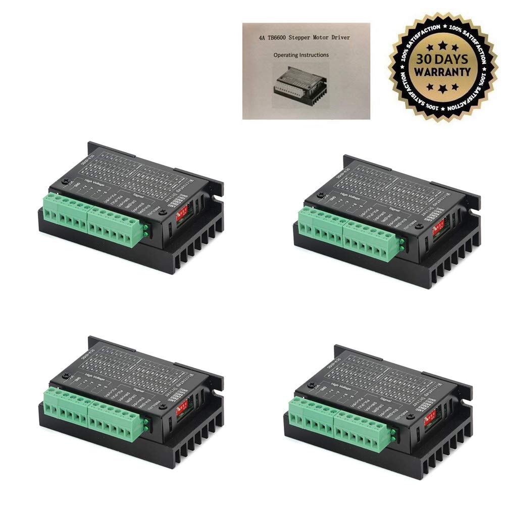
The two crucial things I added are the pendant and the stepper motor drivers.

Once I got all the parts, I needed about 50 hours to assemble and wire the control and to install the limit, home switches, and the touch probe for tool measurement in the machine.
It took another full week to learn and start the Mach4 software, configure the Pokey in Mach4 and make the first part.
The last upgrade I made is that I bought a Chinese 5.5W led laser head, designed and built a bracket to install the laser on the body of the spindle motor, add the necessary connections to the new control and creat a laser machine profile for Mach4 I am delighted with the results although it is a very inexpensive laser device,
Wednesday, December 23, 2015
The Time Transparency Clock
Since the last post I have worked hard in the design and build of the Wood/Plastic clock. I have made a lot of changes in the original design, and I think that the final result is really a very nice clock!

Acrylic is difficult to work in the CNC with small diameter end mill bits. I used a 1/16” 2 Flute carbide end mill for the wheel teeth. After damaging several plastic stock and 2 end mill I learned:
- Use new and sharp bit or a sharp bit that has been used only in plastic. If you used a bit to cut wood, forget to use it later in plastic.
- You need to remove very little material each pass :.
- 24,000 RPM spindle speed and 10 inches/minute feed rate.
- Keep the bit cool with compressed air.
With the above settings, and with lots of patient it is possible to get a very nice and clean cut. Below a video showing the internal cut with 1/8” end mill:
The other complicated thing is to bond brass and acrylic. After several test I ended using 2 part transparent epoxy.
Here is a video showing several details of the clock.
I love the action of this clock!
Happy holidays to all!
Tuesday, November 10, 2015
New Plastic and Wood clock on the way
After some time way from my garage and design activities I am back with a new idea.
This time will be a modernistic table clock design with several interesting features:
- Combination of wood and plastic: The frame, the base and the dial will be made of wood. The wheels will be made of acrylic.
- All wheels will have an outer diameter of 6”
- This clock will have a seconds hand, but a very special one: retrograde seconds hand
- There will be a lot of “action” in the clock as it will have 5 wheels
- Will be driven by a stepper motor and an Arduino controller
Here is the computer design of the clock.
The clock does not have a name so in invite my readers to suggest one.
Sunday, September 6, 2015
Making Mechanical Marvels in Wood with Fusion 360- Part 1
This is an old book! but a very good book for those who want to start building interesting things in wood.
To practice and learn how to use and simulate mechanism in Fusion 360 I modeled all the projects in the book except two.
What I found during this exercises is that Fusion is really friendly and essay to use for and also very powerful. It has some limitations with advance features like motion simulation and contact sets but for general design this things are not very important.
Here are all the models and pictures
Wooden Cam Follower:
The wooden Eccentric Mechanism
Tuesday, August 25, 2015
A Motor model in Fusion 360
The more I play with this software, the more I like it.
The nice thing is that the support and the information available is very good.
I modeled an AC motor to learn to use as much modeling tools as possible.
The program is very similar to Inventor but at the same time more user friendly. It runs slower in my machine compared with Inventor but not a mayor issue.
Below is a very nice tool that allows sharing the projects in a very interactive way.
I hope you like it
Tuesday, August 4, 2015
Autodesk Fusion 360 3D CAD reinvented
I am an experienced 3D drafter. In my day to day work I use AutoCAD, Invertor and SOLIDWORKS. I can switch from one to other without major effort. These programs are all very good and well recognized but at the same time very expensive for personal use. All these programs require to have a computer (powerful) loaded and with the licenses. For big projects you need a server to work on collaboration mode and the price of the license per user is several thousands of dollars a year if you need to keep the software up today.
I have tested many open source 3D drafting programs and also Google SketchUp; some of them pc residents and some cloud based. I did not feel confortable or productive with any of them.
This weekend I downloaded the demo version of Autodesk Fusion 360 and after a couple of hours I registered it and I I fell in love with it. I transferred some of my clocks models to Fusion 360 and started to play around. Then I decided to make a first full drawing of a part, in this case a RC Servo that I will use in a clock. Knowing Inventor the learning process was a piece of cake.
The other good news is that Autodesk Fusion 360 has a very interesting offer: A free 1-year startup license is also available for hobbyists, enthusiasts, makers, and emerging businesses that make less than US$100,000 in revenue per year. At the end of 1 year, you can reselect the startup entitlement or transition to a commercial entitlement.
After finishing the drawing it is necessary to use a program for generate the CAM to be able to mill or fabricate the parts. Mastercam is an excellent program but too expensive for personal use. I don’t know any good machine shop that does not use Mastercam. This program is the standard.
I use BobCad-Cam V26 as CAM postprocessor because I bought it during an offer they had last year at a reasonable price, but I need to convert my work to DWG or STEP in order to run BobCad. The CAD part of BobCad V26 is not as good and flexible as other programs. I know they made a lot of changes in version 27 and probably is much better now but I am not willing to pay more for something I use for hobby and not for work.
Fusion 360 has CAM as part of the package and also has the postprocessor for MACH3 that is the software I use to drive my small CNC. Now the work will be straightforward: Model – CAM – Mill with the same platform.
The next step will be to create a model of a sprocket or wheel and run the cam to learn and test the results with my small CNC machine.
Sunday, July 26, 2015
Conical Clock Overhauled
This clock will go to the hose of a very special person for me and I need it not only to be nice but also accurate. the Conical pendulum is very inaccurate and also has some noise problems. With the changes now the clock is quiet and very accurate.
I modified the clock to be driven by a 60 RPM synchronous motor.
I added a double sided contrate wheel and two crown wheels one driven by the motor and the other to drive the pendulum
The pendulum has also a inertial wheel. I embossed 12 weights to the wheel. I also added a new guide for the pendulum rod.
I really like how it works!
Tuesday, July 21, 2015
Building the planetary clock
One of the things I love best from my profession and my hobby is when I can see in real life what I created in my mind. Technology is great for me because I don’t have the skills to draw by hand in paper so computers and CAD programs helped me to develop my creativity.
Combining technical knowledge with creativity has been the most important tool for my work and now my hobby.
The planetary clock was a challenge. The diameter ratio of the sun pinion to the planet wheels for 12:1 reduction and 8 teeth pinion is at the critical point. Too much play in the teeth can make the system to block as two planet gears can touch each other. Any eccentricity of the ring will block the system and if the teeth spacing is too tight the system will eventually lock itself.
I had to mill more than three times all the parts making small design adjustments to adapt everything to the tolerances for wood. It is almost impossible to obtain tolerances in the range 0 .1 mm with wood so I worked with .5 mm tolerances to allow space for the natural expansion/contraction of the wood temperature and humidity. I also made tests with hot and cool room temperature.
The picture below shows the three planet wheels, the sun pinion, the ring gear, the two ring covers
Below is a detail of the ring covers and the mill down of the sprocket area of .5 mm to allow some play of the planets in the axial direction. This also reduces the friction caused by expansion.
Next picture is detail of the planet gears support, all made form a single piece of wood milled and carved with the CNC to obtain the shape and exact position of the arbor holes.
Here a video of the the testing of the planetary gear: It works nice
Next was to make in the lathe the two circular bases, one is like a cup to hold the motor. The wood I used was so hard that I burned the small motor of the lathe. This is when a full replacement warranty is valuable!
Next finish the wood assemble and glue together everything and pray that it will work as before wood finish. I have found that the best finish for wooden clocks is to use Danish Oil. it is not sticky dries relatively fast it is very easy to apply.
The numbers and the seconds and minutes dashes are engraved in the dial ring:
Here us the clock finished (front view):
Here the back view of the finished clock:
Everything moves very slow in the clock so here are a couple of fast motion videos compressing 3 minutes to few seconds to show how it works:
I love this clock!
Monday, July 20, 2015
Automatic Spindle Speed Control for my CNC
One of the issues I always had with my small CNC 3040 was that I had to manually set the spindle speed in the frequency drive using a knob and chuting the speed with a tachometer. Each tool change or job type (rough or fine) requires different spindl;e speeds.
I found in EBay a small electronic board that converts Pulse Width Modulation to an Analog voltage. It is possible to set the Match 3 software (this is the software that controls my CNC) to output a PWM signal in one of the port pins. The frequency drive can also be set to use a 0 to 10 volts signal to set the motor speed.
This is the link http://www.ebay.com/itm/301557918983?_trksid=p2060353.m2749.l2649&ssPageName=STRK%3AMEBIDX%3AIT
It has some good information in how to calibrate the output.
Below is the small PC board as I installed in the control unit. The circuit needs 24 volts for power that are available in the control’s power supply.
The 0-10 volts output are should be connected to the analog input on the frequency drive:
The PWM input signal to the new circuit should be connected to one of the output pins. in my case I used the A axis on the CNC control board hat corresponds to the output pin 9.
On the mach 3 software it is necessary to adjust the following settings:
The last part is to set the frequency drive parameters to allow speed control via the analog input. The drive of my machine is a Chinese HUANYANG ELECTRIC
I spent a lot of time searching in the Internet for a manual until I found it in a Chinese site. Thanks to Google automatic page translate!
These are the parameters to change:
PD0000 set to 1 to be able to make changes
Pd002 set to 1 to use the external terminal
PD070 set to 0 to use 0-10V control
Once it is running it is necessary to calibrate the output using the potentiometer in the new circuit
The system works OK although it is not very linear but for milling plastics, wood and soft metals it is OK. I am very happy and it is working really good and helping me to avoid mistakes.