Wednesday, November 26, 2014

New Toy In My Garage

The more I work with wood, the more I love it. I started to make new thing and found that they were almost impossible to make without a lathe.

I found in Amazon a device that can be installed in the press drill to make lathe work. It is very inexpensive so I bought it and stared to work and learn.

2014-10-12 16.07.19

Very soon I found that this is good for eventual work but first it is no easy to work in the vertical position and the tool rest, that is a tube in a fixed position parallel to the rotation axis is a big limitation.

Then I found in   Harbor Freight Tools Discount Tool & Hardware Store this beautiful mini lathe that at the time was on offer for an incredible low price

Central-Machinery 95607 8" x 12" Bench Top Wood Lathe

I bought the tooling in Amazon, build a table and place it in my garage next to my press drill


2014-10-17 17.05.45


I have been very busy with real life work but I have been able to find time to play with my lathe.

I will continue to post my leanings when I find a some time.

Friday, September 19, 2014

The Conical Clock is ready!

Due to health and other reason I have been away from my garage for some time but now I am okay and I finished the clock and already started wit a new project Sonrisa

A picture is worth a thousand words so here are some:

IMG_6290

2014-09-19 18.44.342014-09-19 18.45.37 - Copy

And here the video of this beautiful clock! I am really proud of this work Enamorado


Thursday, April 17, 2014

The Conical Pendulum Wooden Clock Part 6

The conical clock fully functional!

image

Images tell more than million words Sonrisa

  • New pendulum support arc design: more stable and stronger
  • New bevel gear design: Allows more play and wood imperfections, runs smoother than the original design
  • Speed control plate
  • Elliptical clock dial
  • Elliptical clock hands

Still missing:

  • Lower decorative arc
  • wheel stoppers
  • wood finishing
  • brass pendulum polishing

I am really proud and happy with this project and I imagine the Clyton Boyer will enjoy the implementation of his basic idea that was draft paper few months ago. I hope I was able to intemperate and visualize his concept by making it a real clock using a new driving technology. As far as I know this is the first Conical Wooden Clock! 

In few days I will go back to the hospital for a second surgery (this one is to bring me back to normal conditions by removing  an ostomy bag and fix some abdominal issues) so I will be out of my garage for some time.

Update 4/18/2014:

Clyton Boyer email:

After Clyton saw this post he wrote to me:

“…SO Excellent, Carlos.  Yes, I believe it is the only wooden conical also.  I have seen a lot of conicals, and I've been to many clock museums or museums with clocks, and I've never seen my dream of a wooden conical realized...until NOW! and I love it.  I am so happy that you took on this design and added your ingenuity to it and helped to create my dream (and apparently YOUR dream, as well).

I really like the way it looks and all of the personalizations that you have added to it, like the oval dial, the bevel gears, and many other smaller changes (and of course, your very own self-created motor!!!  That's no small task!)

The conical design really looks so beautiful and there is so much action.  I truly appreciate your dedication and what you have done to create the conical in real life.  It's a beauty.

Good luck with your second surgery.  Hopefully all goes very well and you will be up and back in the shop very soon.

Thanks for keeping me informed on your project.  It is so much fun!…”

And in a previous mail when I was sharing with him the first tests he wrote:

“…The motor-driven conical pendulum clock that you have built is truly wonderful.  I showed all the vids to my wife.  She has given you build a "Two Thumbs Up!" approval, and thinks it looks "really neat!"

I have to agree.  I've always liked that design, and have always been tempted to build it, but now that I see it in action, I'm even more motivated.  I'm glad it worked well with the motor you designed to drive it.  I would, of course, drive mine with rocks...paleolithic style.  Ha.  Or this might also be a nice constant force spring-driven design in a tabletop version.  But as you mention, conical pendulums have an inherently inaccuracy in their design, and none would be anywhere near as accurate as your motor driven version.

It is SO lovely to see a vision that I only had in my head come to life!  Thank you for your passion on this project.  It is wonderful to share with other builders that share the same passions.

Beautifully done, Carlos!!!…”


I only have to say to Clyton:

Thank you very much for introducing me to this amazing hobby! This has been the most amazing and pleasure providing creative activity I have ever performed. My brain is exploding with ideas and new projects. I never thought that there were so many  artistic and creative neurons active in my brain. 

The Mechanical Speed Control for the Conical Pendulum

There is a basic difference between the classic pendulum and the conical pendulum:

image

In the classic pendulum and for small swings the period of swing is approximately the same for different size swings: that is, the period is independent of amplitude. This property, called isochronism, is the reason pendulums are so useful for timekeeping. Successive swings of the pendulum, even if changing in amplitude, take the same amount of time. The basic formula for the ideal pendulum is:

image

So for small swing angles (much less than 1 radian (57 degrees) the period of the oscillation will depend basically of the length on the pendulum.

In the conical pendulum: the period of rotation for small angles θ is determined by the length of the pendulum.

image

The formulas for the conical pendulum are:

image

Where t is the period of revolution

This formula can be expressed as:

image

When applying a force to keep the pendulum rotating, there will be a centrifugal force that will increase the angle θ so h will be smaller as the angle increases and the period of revolution will be smaller. In theory for small forces there will be equilibrium and the angle and the speed will be constant (for small angles).

In real life and with imperfect arbors and wood susceptible for changes by temperature and humidity the equilibrium point will constantly change. Sometimes, when the friction is low the pendulum will rotate faster  (larger angle) and when there is more friction the speed will be slower (smaller angle) because we are applying a constant rotation torque with the impulse motor.

The above means that the conical pendulum is intrinsically inaccurate for time keeping unless we add some kind of regulation and this has been the challenge for all conical pendulum clock designs since they were invented. The patent of J. C. Briggs in 1885 is related to a speed control device that increases the friction as the angle of the pendulum grows. But in reality this is basically what the Watt’s speed governor does.

My challenge was to find a way to make a very simple speed control for my conical clock and I did it!

I added a small piece of wood cut in a parabolic shape. The pendulum rod’s tip will hit the piece of wood when the angle increases due to speed and this will force a reduction of the angle and will slow down the rotation speed.

image

In the flowing slow motion video (1/8th of the real speed where on revolution is 8 seconds) you can see how this device works and slows down the pendulum speed.


Thursday, April 3, 2014

The Conical Pendulum Wooden Clock Part 5

Las few days in the garage were 100% dedicated to mill the wheel and pinions of the clock train and today I finished and mounted all of them with their arbors in the frame.

The clock looks really beautiful RelojSonrisa

2014-04-03 16.56.56


2014-04-03 16.57.46

I still need to glue the pinions and wheels to the support , also polish the arbors to minimize friction and make the stoppers for the wheels.

Next step is to make a provisional vertical support (The clock is a wall mounted clock), fix the clock to that provisional wall, install the pendulum and start testing.

Friday, March 28, 2014

The Conical Pendulum Wooden Clock Part 4

Experimenting with a Wooden Bevel Gear

The original Clyton Boyer’s drawings was using a crown pinion and a wheel using rods as the teeth and this is what used for my initial design as shown in the picture from my 3D model below:

image

Later I thought that it would be an interesting challenge to make a wooden Bevel Gear instead of using the wheel with rods.

Making this with wood and by hand is very complicated but with the CNC is quite a simple task. After a couple of hours of design and CNC programing I was able to mill the pinion and the wheel really fast. Below a video of my CNC milling the wheel:

I made an initial design and test and this is how it looks like:

2014-03-28 17.57.22

And it works! Desternillado de risaPulgar hacia arriba as seen in the following video:

There is still work to do as all the mounting is provisional, I need to build the proper wood spacers, the pinion of the wheel to drive the rest of the clock, the stopper. I need to cut the holes to reduce weigh on the wheel and I need to mill a new motor pinion as there is a mistake on the diameter of the hole so it fit loose in the motor shaft.

Anyway the important thing is that the concept works and this will be integrated in the clock.

Update:

I just finished the final version of the bevel gear and tested it with the pulse motor installed in the clock frame at full speed without the pendulum. The result is really nice and works quite and smooth

Here are some close-up views of the gears:

 2014-03-29 20.31.23


2014-03-29 20.31.30

2014-03-29 20.31.39

Thursday, March 27, 2014

The Conical Pendulum Wooden Clock Part 3

Scroll Saw Weekend:

In order to start the building and assembly of the clock it is necessary to have the back base or frame first be able to mount the rest of parts. I designed this frame using elliptical curves and it was not easy to cut with the saw as I deiced to use oak that is not an easy wood to work and the width is 3/4”.

This is a 3D view of the frame from my CAD software

image.

First I made a paper template scale 1:1. As I don’t have a plotter or a printer for large paper I split the drawing in several sheets


2014-03-26 11.04.30

I glued the template to the board and start cutting very slow.. 3/4” oak requires tons of patient if you don’t want to spend your savings in saw blades and ruined wood…

The first cut was the outside, then the internal, and this was really difficult and a lot of work!

2014-03-26 12.02.38

After the internal cuts I drilled the holes for the arbors and the dial support using the same template.

2014-03-26 14.00.23

Finally sand paper to remove the imperfections of the cut (that were a lot…)

Anyway I am very happy with the results at it is a very nice and original frame for my conical clock Sonrisa

There is still a lot of sanding needed for finishing but this will be after the clock is fully tested.

2014-03-26 21.14.02

Monday, March 24, 2014

The Conical Pendulum Wooden Clock Part 2

This weekend was very active and productive. I have the pendulum up and running Sonrisa

First was to wind the coil and fix it in place. I made the coil reel using a 1/4” brass tube and for the sides I cut two circles of 1” diameter of 1/16” plywood.

 2014-03-23 14.47.42

The screw in the center of the coil  is not for fixation  which, I  fixed it to the base with double side glue duct tape. The function of the screw is to adjust to torque of the pulse motor.

Then I wired the driver circuit and the optical switch.

2014-03-24 13.44.56

After testing the motor without the pendulum I milled  and installed the pendulum slotted guide in the rotor, hanged the pendulum and started to test and calibrate the height of the bob and the torque of the motor. I set it to run at exactly one second per turn with the help of the oscilloscope.

I had to reinforce the arcs as they were moving and oscillating  with the pendulum movement so I added a vertical wood support to hold the arcs at the top. Now I must think in a way to make some kind of reinforcement in the final design of the clock in order to hide this support.

Here is a video of the pendulum working and running very precisely Sonrisa:

And this is a slow motion video of the pendulum at 1/8th of the speed. A full turn will be 8 seconds:

Now I have to go back to the drawing table (My Computer) modify the final design with the new pendulum and find a way to reinforce the arcs structure without affecting the beauty of the design.


See you soon in my garage!

Saturday, March 22, 2014

The Conical Pendulum Wooden Clock Part 1

Now that the pendulum is tested I am starting the building of the real clock. The 3D design is ready although I still need to modify it based on the leanings of the test stand. This design is based  in a draft that Clyton Boyer shared with me of a conical pendulum clock using constant force spring. He never finished the design and he gave it to me to see if I can convert it to the electrical driven conical pendulum. (And I took his as a challenge)

Using Clyton’s basic idea I redesigned the back base, also designed the elliptical dial. I changed the position of the wheels in order to match the base and the dial shape. I also defined the arbor’s length and decide to use 3/16” rod for the arbors instead 1/8”

These are some views  generated by the 3d design software I use:

Conical ISOconical frontconical back

This weekend I started with the building of the real clock. The first thing is the pendulum, once I have it ready, tested and calibrated I will continue with the rest of the clock.

This is the Final design of the pendulum part of the clock after the leanings from the test stand

image

In this opportunity I went back to basics and used a scroll saw to cut the base parts and the arcs. I only used the CNC for carving the holes for the motor, the ball bearings and electrical circuit (added space for eventual use of batteries)

  2014-03-22 11.51.082014-03-22 11.52.162014-03-22 11.52.07

Today I finished the pendulum structure an this is how it looks now:


2014-03-22 20.51.32

Tomorrow I will finish the electrical part, hang the pendulum and start testing!

Wednesday, March 19, 2014

The Conical Pendulum

A little bit of history and theory:

After a couple of months out of my garage due to colon cancer surgery (fortunately cancer is gone!) I am slowly acquiring strength  and returning to my garage to continue with passion.  I still cannot return to my normal work activity until a couple more months so I can dedicate a lot of time to the development of my hobby.

Conical pendulum clocks are part of the clock history but as they are not easy to implement you don’t see too many around, and as far as I know there are no wooden conical pendulum clocks.

The concept was patented by J. C. Briggs in 1885 but the French already built  conical pendulum clocks some of them as far as 1869

This is the Briggs Rotary pendulum clock:

And tis is a typical French conical pendulum:

The angle and the height of the pendulum bob is related to the period of a revolution by the following formulas (this is for an ideal pendulum):

conical pendulum diagram

image

The rotational speed will be slower for a longer pendulum and for a fixed length “T” a smaller radius “r” will make the pendulum to turn slower because the height “h” will increase as the radius decreases.

Conical clock are usually driven by a windup system with constant force springs but my idea is to combine the concept of the pulse motor with the conical pendulum. I also wanted to make a one second period pendulum to be able to build the wooden clock with reasonable size wheels. in this case I will replace the escapement wheel by a set of crown wheels. Clyton provided me with some draft drawings of a wooden conical pendulum clock. I will try to use his basic initial design adding my motorized conical pendulum and as much of my creativity I can to explode and convert his original idea in a reall wooden conical clock.


The Motorized Conical Pendulum Prototype:

Before staring the construction of the clock I needed to make a lot of experimentation so I designed a test stand to first test the motor without pendulum and then to test the pendulum.

image

The original design had a wooden rotor with 4 Neodymium magnets and two coils, one for pickup an the other as an actuator. The electricity induced in the pickup coil when one of the magnets was passing trough the core of the coil generates an impulse that is used to turn on a transistor to make the current to flow in the actuator coil. This will create a magnetic field to attract  or repel (depending on the coil orientation) the magnet, this will create a rotary motion.

image

At the end and after many tests I decided to eliminate the pickup coil and use an optical switch activated with an optical cam. In this video I show the first version of the test stand. Here it is is running faster than 1 sec/rev. It took me almost three week to get a perfect working model.

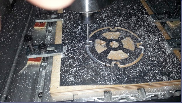
The final design is the result of lots of modifications and tests. But the important thing is that now I made all the learning and understood all the necessary to make a final working design in wood. I added ball bearings, I changed the height and the design of the pendulum rod. I found the optimal design of the optical cam. To optimize the development speed I used acrylic and aluminum to make most of the parts and this was a very good opportunity to learn how to work with different materials with my CNC.

My CNC milling aluminum:

2014-03-11 12.51.54

The rotor made with acrylic and aluminum:

2014-03-13 18.35.32

In this Video I show the final version of the Conical Pendulum, running at 1 second per revolution.


Art or Technology?

The  trick to make the motorized conical pendulum to run at the correct speed is to set the motor to deliver the exact amount of torque for the pendulum to do its job. If too much torque is applied then the pendulum will reach to the top angle due to the centrifugal force but the motor will continue to accelerate. If not enough torque is provided then the pendulum will eventually stop. Some people have asked me why I did not use a microcontroller like the Arduino to monitor the speed and adjust the torque. My answer is that using this high tech will make the pendulum a dummy device, I could use a simple servo motor controlled by the Arduino to move the clock or buy a Chinese clock motor to drive the wooden clock! I like the art and the challenge to make the things to work in the simplest way possible. The old clock makers like Briggs did not have an Arduino and they were capable to design a very accurate time keeping machine. My goal here is to find an electrical substitute for the constant froze spring and this, from my Point Of View, is Art!